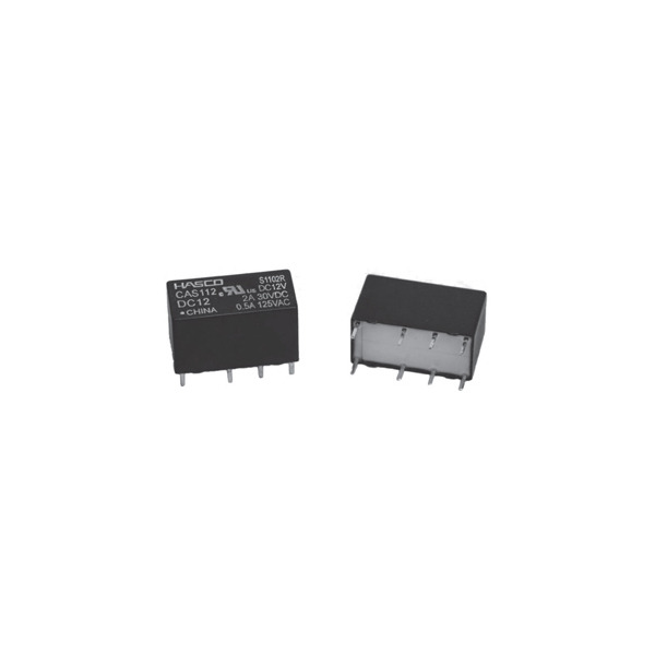
Description
Contact Ratings
| Contact Arrangement | 2C |
| Contact Resistance | 50mΩ(0.1A 6VDC) |
| Contact Material | Silver Alloy, Gold Flash |
| Contact Rating(Resistive) | 2A/30VDC 2.5A/12VDC 0.5A/125VAC 0.6A/120VAC |
| Max. Switching Voltage | 150VAC/125VDC |
| Max. Switching Current | 2A |
| Max. Switching Power | 75VA/60W |
| Mechanical Life | 1×10⁸ operations |
| Electrical Life | 1×10⁵ operations |
Ordering Information

Characteristics
| Insulation Resistance | 1000MΩ (at 500VDC) | |
| Dielectric Strength | Between coil & contacts | 1000VAC 1min |
| Between open contacts | 1000VAC 1min | |
| Operate time (at nomi. volt.) | ≤7ms | |
| Release time (at nomi. volt.) | ≤5ms | |
| Humidity | 98% RH, 40°C | |
| Ambient temperature | -25°C ~ +85°C | |
| Shock Resistance | Functional | 100m/s2 |
| Destructive | 980m/s2 | |
| Vibration resistance | 10Hz ~ 55Hz 1.5mm DA | |
| Unit weight | Approx. 5g | |
| Construction | Sealed Type | |
Notes:
1) The data shown above are initial values.
2) Please find coil temperature curve in the characteristic curved below.
Coil Data at 20°C
Standard Type
| Nominal Voltage VDC |
Pick-up Voltage (Max.) VDC |
Drop-out Voltage (Min.) VDC |
Max. Allowable Voltage VDC |
Coil Resistance Ω±10% |
|---|---|---|---|---|
| 5 | 3.5 | 0.5 | 7.0 | 45 |
| 6 | 4.2 | 0.6 | 8.4 | 66 |
| 9 | 6.3 | 0.9 | 12.3 | 140 |
| 12 | 8.4 | 1.2 | 17.4 | 280 |
| 24 | 16.8 | 2.4 | 34.0 | 1070 |
| 48 | 33.6 | 4.8 | 64.9 | 3900 |
Sensitive Type
| Nominal Voltage VDC |
Pick-up Voltage (Max.) VDC |
Drop-out Voltage (Min.) VDC |
Max. Allowable Voltage VDC |
Coil Resistance Ω±10% |
|---|---|---|---|---|
| 5 | 3.5 | 0.25 | 12.5 | 167 |
| 6 | 4.2 | 0.30 | 15.0 | 240 |
| 9 | 6.3 | 0.45 | 22.5 | 540 |
| 12 | 8.4 | 0.60 | 30.0 | 960 |
| 18 | 12.6 | 0.90 | 40.0 | 1620 |
| 24 | 16.8 | 1.20 | 52.9 | 2880 |
| 48 | 33.6 | 2.40 | 84.9 | 7680 |
Coil
| Coil Power | Standard Type:500mW ~ 590mW |
| Sensitive Type:150mW ~ 300mW |
Safety Approval Ratings
| UL&CUL | 2A/30VDC, 0.6A/125VAC |
Outline Dimensions, Wiring Diagram And PC Board Layout Unit: inch(mm)
| Outline Dimensions |
|---|
 |
| Wiring Diagram (Bottom view) |
 |
| PCB Layout (Bottom view) |
 |
Remark:
1) In case of no tolerance shown in outline dimension: outline dimension ≤1mm,tolerance should be ±0.2mm; outline dimension >1mm and ≤5mm,tolerance should be ±0.3mm;outline dimension >5mm, tolerance should be ±0.4mm.
2) The tolerance without indicating for PCB layout is always ±0.1mm.
Characteristic Curves
 |
 |
 |