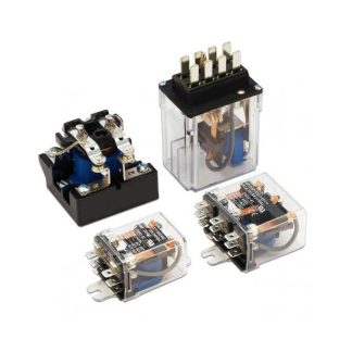
Description
Contact Ratings
| Contact Arrangement | 1A、1C | |
| Contact Resistance | ≤100mΩ (1A 24VDC) | |
| Contact Material | AgNi, AgSnO2, Silver alloy | |
| Contact Rating(Resistive) | NO:20A 277VAC NC:16A 125VAC |
NO:25A 125VAC 17A 277VAC NC:20A 125VAC |
| Max. Switching Voltage | 400VAC | 400VAC(NO) |
| Max. Switching Current | 20A | 25A |
| Max. Switching Power | 4700VA | 5540VA |
| Mechanical Life | 1×10⁷ operations | |
| Electrical Life | 1×10⁵ operations | 5×10⁴ operations |
Ordering Information

Characteristics
| Insulation Resistance | 100MΩ (at 500VDC) | |
| Dielectric Strength | Between coil & contacts | 2500VAC 1min |
| Between open contacts | 1000VAC 1min | |
| Surge voltage(between coil & contacts) | 6kV(1.2×50μs) | |
| Operate time (at nomi. volt.) | ≤10ms | |
| Release time (at nomi. volt.) | ≤5ms | |
| Humidity | 5% ~ 98% RH | |
| Ambient temperature | Class B:-40°C~85°C; Class F:-40°C~105°C | |
| Shock Resistance | Functional | 98m/s2 |
| Destructive | 980m/s2 | |
| Vibration resistance | 10Hz to 55Hz 1.5mm DA | |
| Unit weight | Approx. 14g | |
| Construction | Sealed Type, Dust Cover Type, Flux Free Type |
Notes:
1) The data shown above are initial values.
2) Please find coil temperature curve in the characteristic curved below.
Coil Data at 23°C
| Nominal Voltage VDC |
Pick-up Voltage (Max.) VDC |
Drop-out Voltage (Min.) VDC |
Max. Allowable Voltage VDC |
Coil Resistance Ω±10% |
|
|---|---|---|---|---|---|
| 20A | 25A | ||||
| 3 | 2.25 | 0.3 | 3.9 | 25 | 20 |
| 5 | 3.75 | 0.5 | 6.5 | 70 | 55 |
| 6 | 4.50 | 0.6 | 7.8 | 100 | 80 |
| 9 | 6.75 | 0.9 | 11.7 | 225 | 180 |
| 12 | 9.00 | 1.2 | 15.6 | 400 | 320 |
| 18 | 13.00 | 1.8 | 23.4 | 900 | 720 |
| 24 | 18.0 | 2.4 | 31.2 | 1600 | 1280 |
| 48 | 36.0 | 4.8 | 62.4 | 6400 | 5120 |
Coil
| Coil Power | 20A:360mW 25A:450mW |
Safety Approval Ratings
| UL&CUL | NO | 20A | 20A/277VAC GP Load TüV 10A/120VAC, 5A/240VAC Resistive Load |
| 25A | 25A/125VAC, 17A/277VAC GP Load 1500W/277VAC Ballast, 1700W/120VAC Tungsten |
||
| NC | 20A | 16A/125VAC GP Load 10A/120VAC Resistive Load |
|
| 25A | 20A/125VAC GP Load 1500W/277VAC Ballast, 1700W/120VAC Tungsten |
||
| TüV | NO:16A/250VAC; 50/60Hz NC:10A/250VAC; 50/60Hz |
Outline Dimensions, Wiring Diagram And PC Board Layout Unit: inch(mm)
20A
| Outline Dimensions |
|---|
 |
| Wiring Diagram (Bottom view) |
 |
| PCB Layout (Bottom view) |
 |
25A
| Outline Dimensions |
|---|
 |
| Wiring Diagram (Bottom view) |
 |
| PCB Layout (Bottom view) |
 |
Remark:
1) In case of no tolerance shown in outline dimension: outline dimension ≤1mm,tolerance should be ±0.2mm; outline dimension >1mm and ≤5mm,tolerance should be ±0.3mm;outline dimension >5mm, tolerance should be ±0.4mm.
2) The tolerance without indicating for PCB layout is always ±0.1mm.
Characteristic Curves
20A
 |
 |
 |
25A
 |
 |
 |